Designer’s Choice
Designer’s Choice
Entry ID: 164The most popular of Newood’s perimeter wall display systems is Designer’s Choice. The perfect choice to start any FF&E (Furniture Fixtures and Equipment) package. Architects, store planners and store owners can choose from hundreds of pre-engineered fixture parts to form a custom looking display wall that meets their appearance and display requirements. Designer’s Choice starter and add-on components ship KD for assembly in store, saving crating costs, lowering freight costs and minimizing possible damage occurrences.
Newood’s experienced staff will help you choose the preferred wall system, wall parts, provide a floor layout, estimate the fixture cost and freight cost at any time in the design process. There is no extra charge for help designing your store layout using our standard wall display or floor systems.
Designer’s Choice is a proven wood display shelving system that provides maximum design, finish and display options that meet ever changing retailing display need. Achieve the preferred look and functionality you want by selecting variety of standard components. Then, dress up your store by adding moulding special features, finishes and accents that match or complement your store interior. We encourage you to contact our experienced staff early in the design process. Please call 800-233-9663 for help today!
A complete PDF file of the Designer's Choice system can be downloaded here: 
Several Priced Examples can be seen here:
Step-by-Step guide for designing perimeters with Designer’s Choice Perimeter System:
1. Determine the best cabinet depth for each space. Depths offset in 4" increments. (10" - 14" - 18" - 22" - 26")
2. Determine the best cabinet height for each space. Heights offset in 10" increments. (82" - 92" - 102")
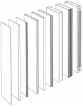
3. Choose upright thickness or combinations of thicknesses.
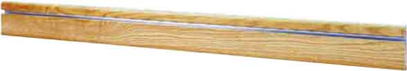
4. Choose design detail for upright front edges. (3/4" taped edge - 6" moulding)
5. Choose header height and detailing. Headers are not required when top caps are used. Header heights are 3-1/4" or 6-1/2".
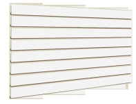
6. Determine best cabinet width and height which determines the length of kickboards and headers and the size of backs. Backs can be plain or slatwall.
7. Choose top cap detail, if included in the design. If headers are not used, top caps are required.
8. Choose Oak or Maple with clear lacquer or stained finish. Some designs are also available in wood-grained Oak or Maple Melamine.
9. Choose optional laminate (+) or color stripe (=).
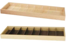
10. Choose accessories.
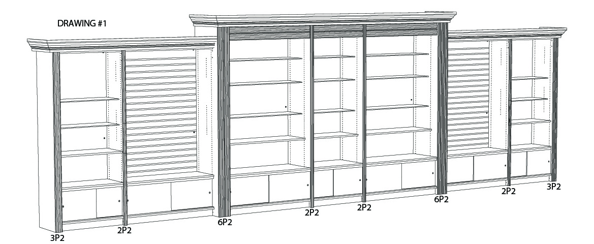
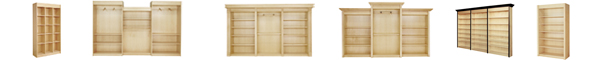
Example of a run of Designer’s Choice Perimeter System:
Drawing #1 illustrates one of many possible configurations and combinations of parts to create an attractive and versatile fixture run. Note that Headers are used in the center section only. Top Caps are optional when Headers are used and Headers are optional when Top Caps are used. Both Headers and Top Caps can be used for a heavier and more elegant look.
1. This run was designed with a combination of Upright thicknesses, depths and heights to add to the visual appeal.
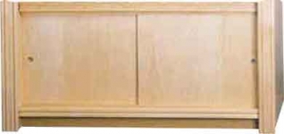
2. Headers (used in center) usually match the moulding pattern applied to the front edge of the Uprights. Top Cap moulding is fabricated and precut for assembly onsite. See Top Cap moulding options. All units in Drawing #1 have
optional Door Kits for overstock storage. In this run, two slatwall backs and five standard backs are used. The accessories shown are typical of most installations.
3. For each run we provide a layout drawing as illustrated in Drawing #2 (same configuration as Drawing #1). Upright location is identified by letters (A, B...). Installers match the letter marked on each Upright to the letter shown on the drawing (A to A) (B to B), etc.. Below is a description of each upright.
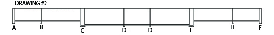
A - Left end Upright: 3" W x 18" D x 82" H with 3-1/4" Moulding Pattern 3P2 front - Qty (1)
B - Inside Upright: 3/4" W x 18" D x 82" H with 1-3/4" Moulding Pattern 2P2 front - Qty (2)
C - Left Transition Upright: 6" W x 22" D x 92" H with 6-1/2" Moulding Pattern 6P2 front - Qty (1)
D - Inside Upright: 3/4" W x 22" D x 92" H with 1-3/4" Moulding Pattern 2P2 front - Qty (2)
E - Right Transition Upright: 6" W x 22" D x 92" H with 6-1/2" Moulding Pattern 6P2 front - Qty (1)
F - Right end Upright: 3" x 18" D x 82" H with 3-1/4" Moulding Pattern 3P2 front - Qty (1)
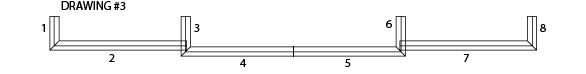
Drawing #3 represents a typical top cap plan view. All top cap (crown moulding) is sent with a 3" horizontal back plate attached. Parts are pre-cut to exact size and angle needed, ready to be installed. Each top cap part is marked with a number (1, 2, 3, etc.). At the job site, the installer matches the part number to each number shown on the top cap layout.
Pieces and Pricing
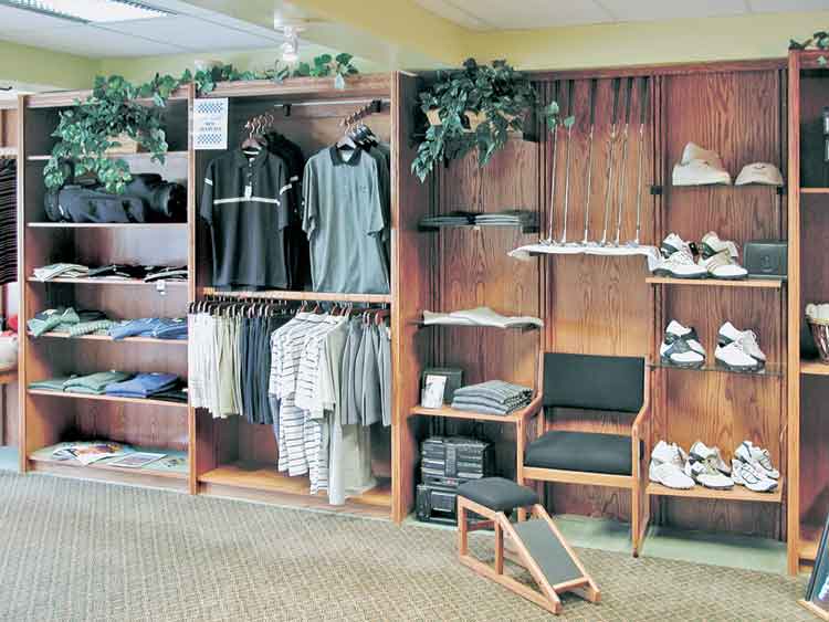
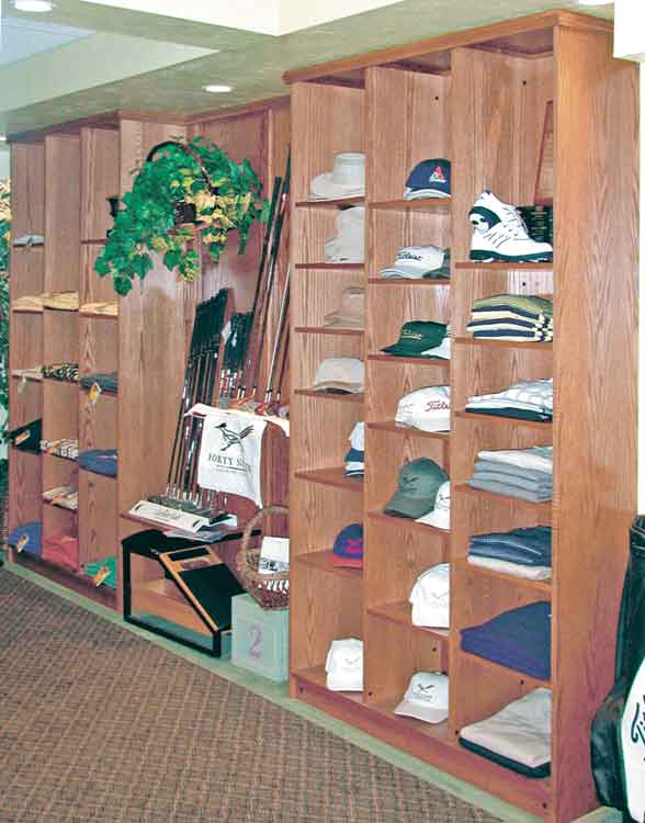
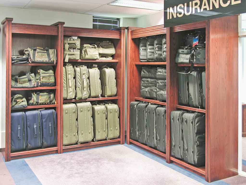
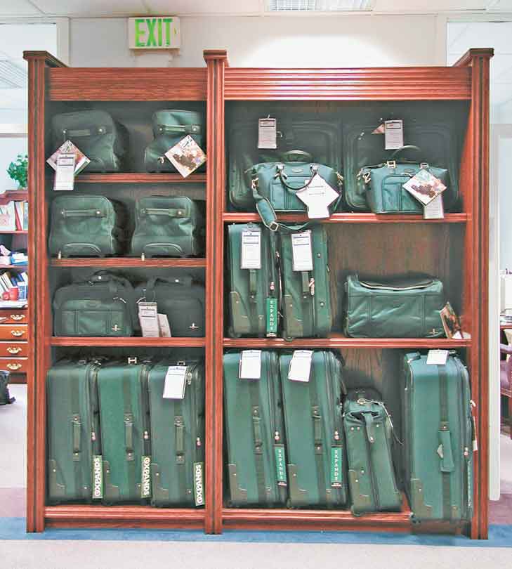
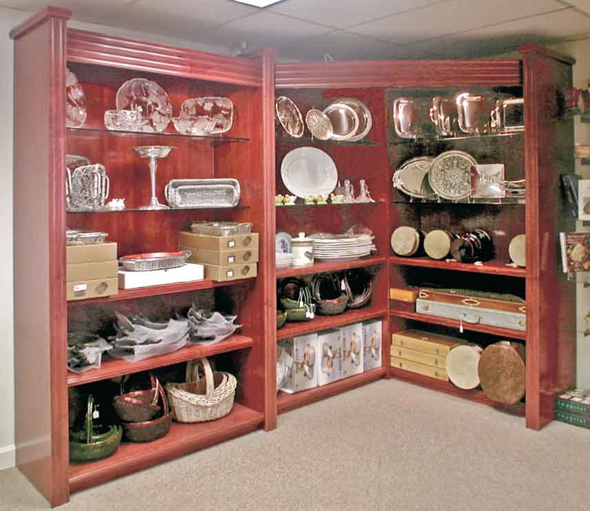
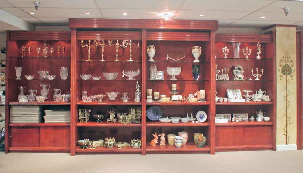
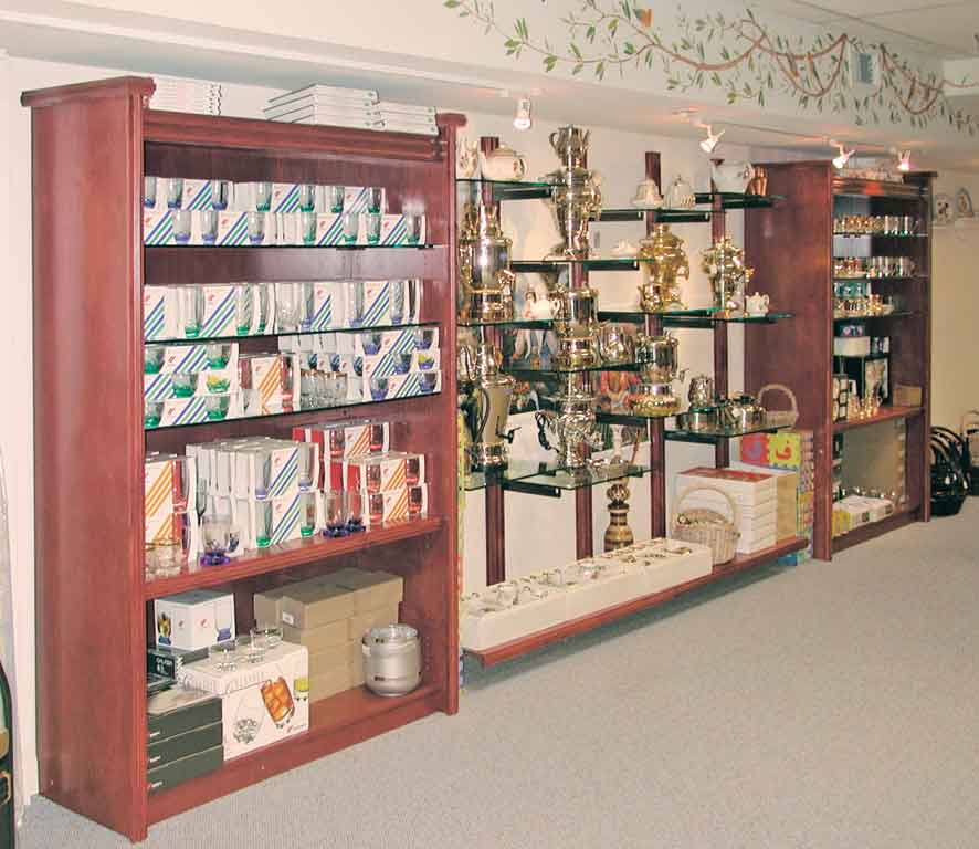
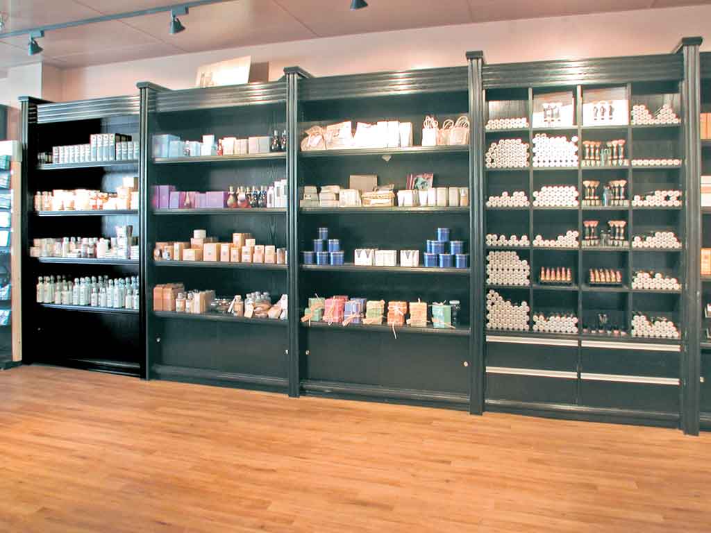
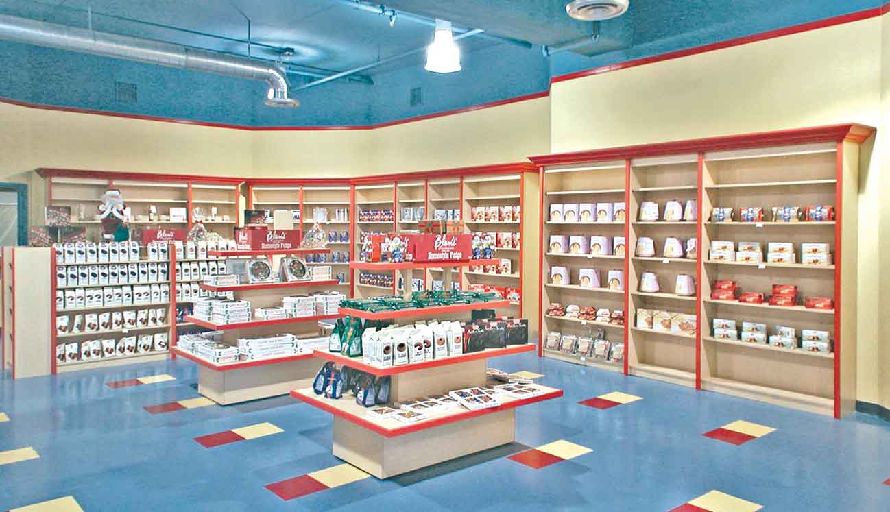
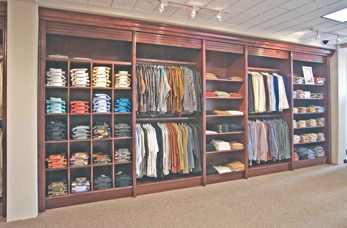
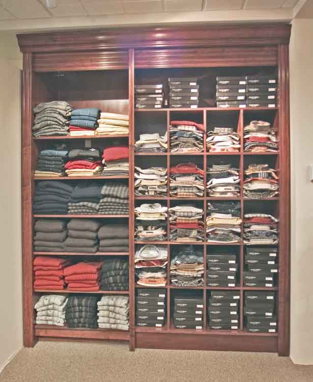
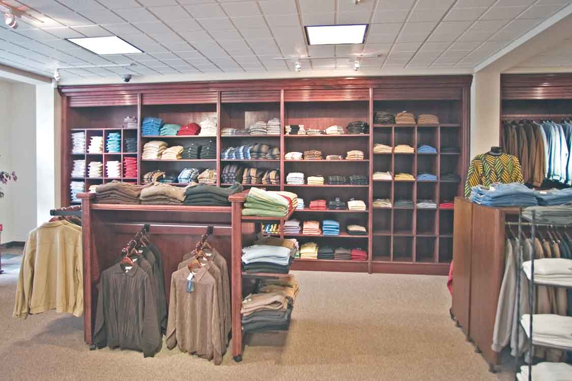
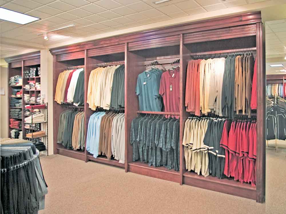
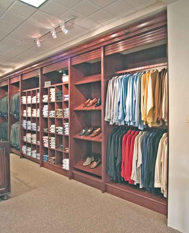
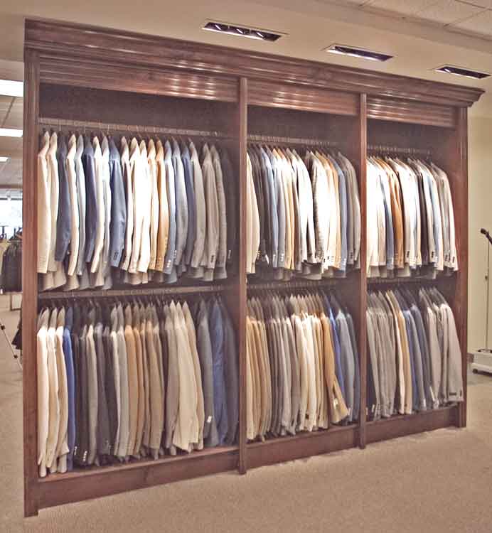
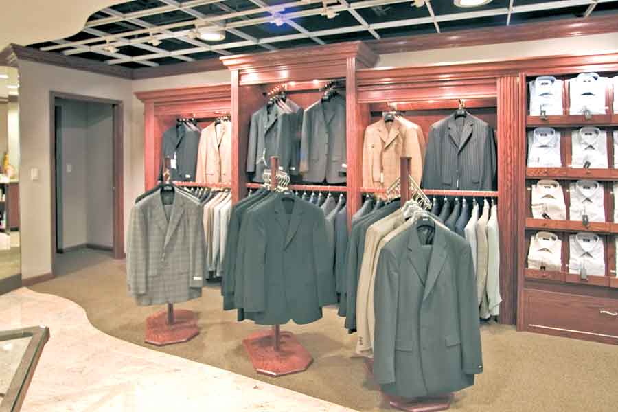
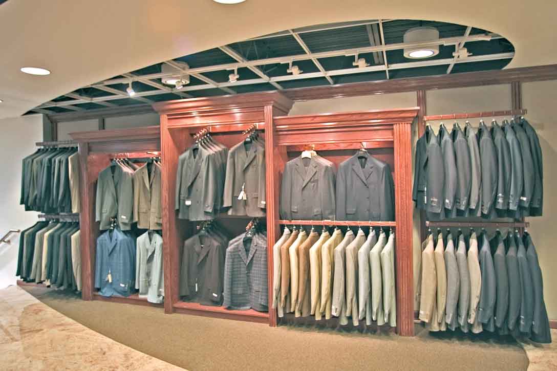
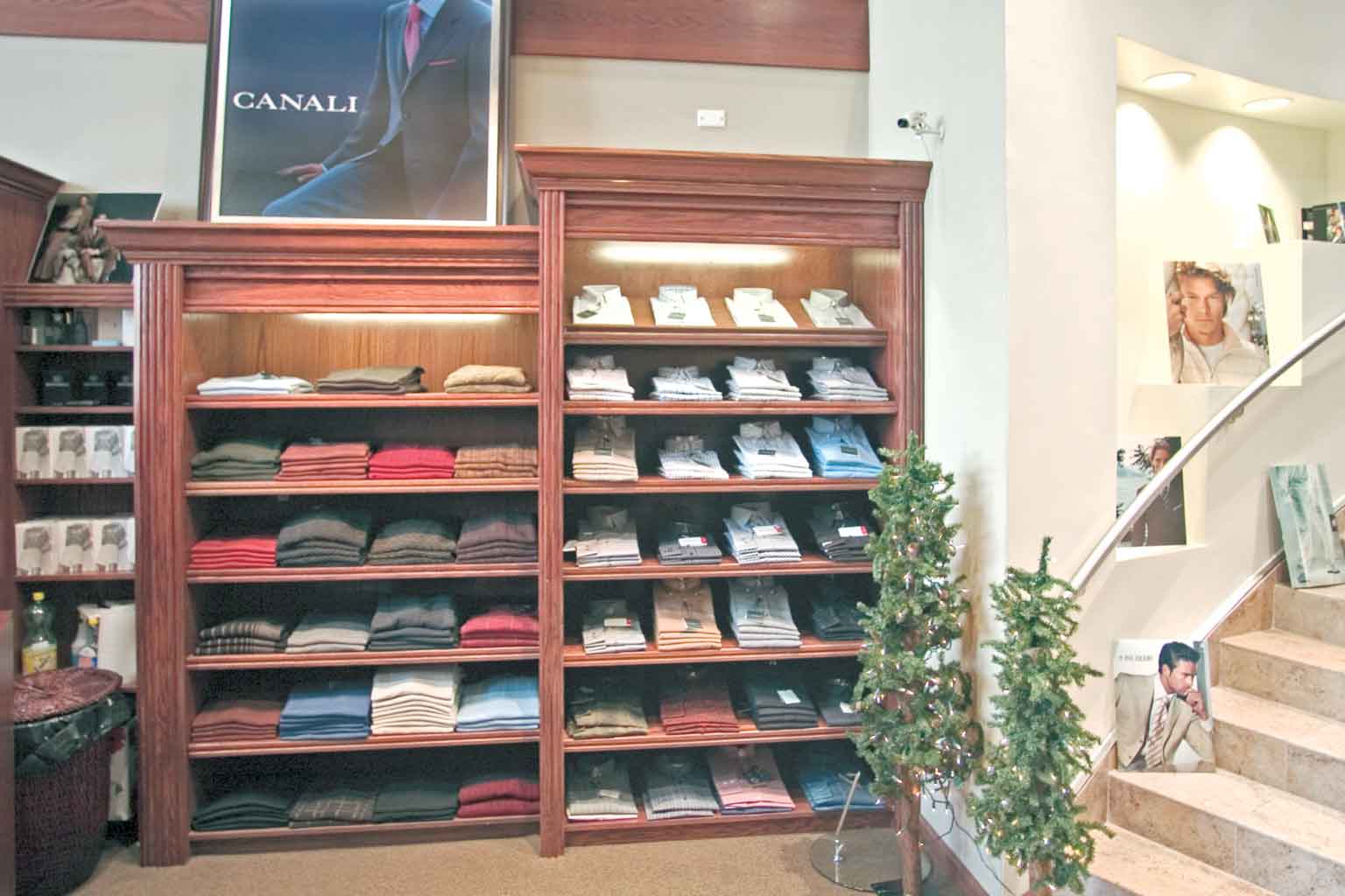
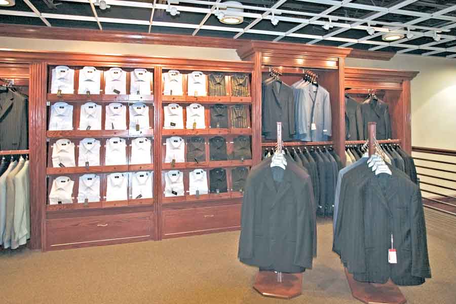
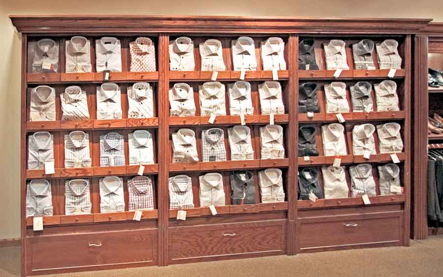
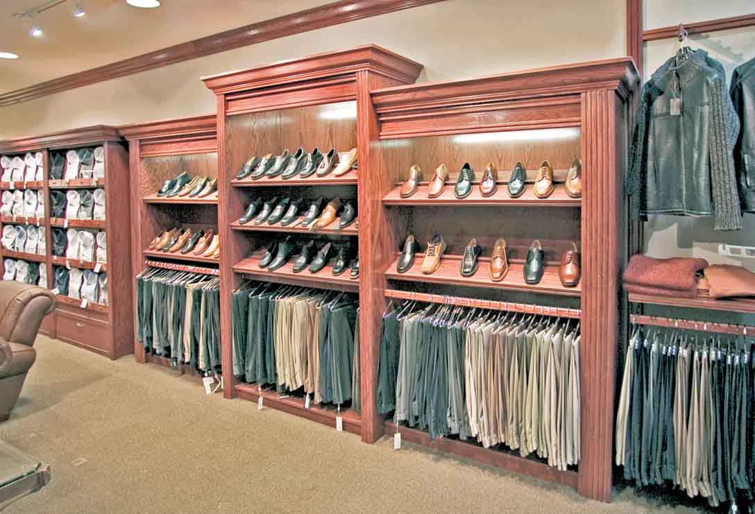
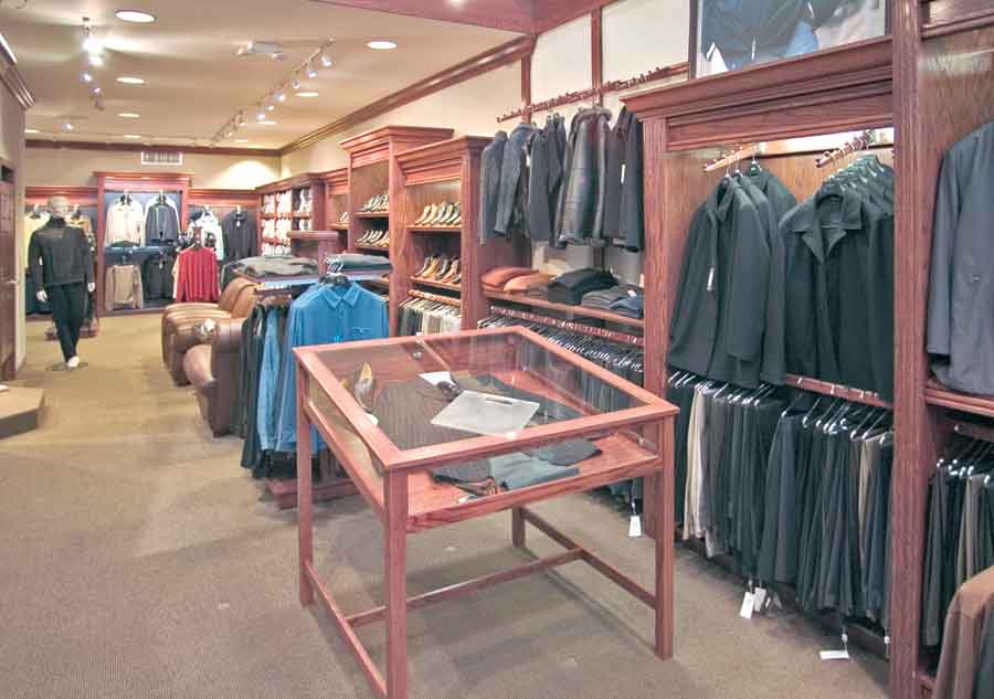
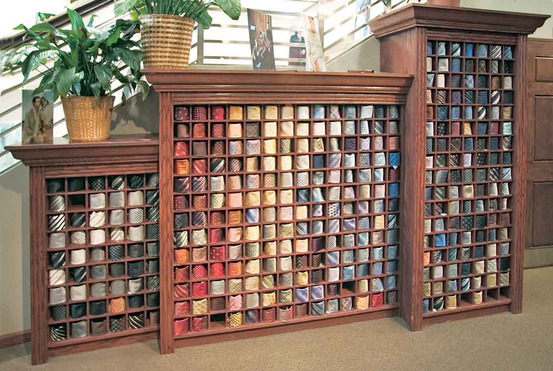
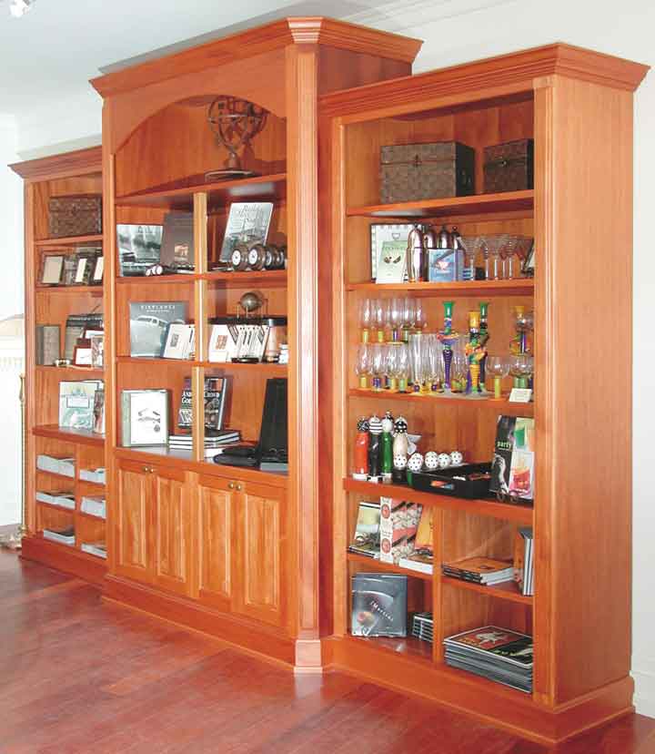
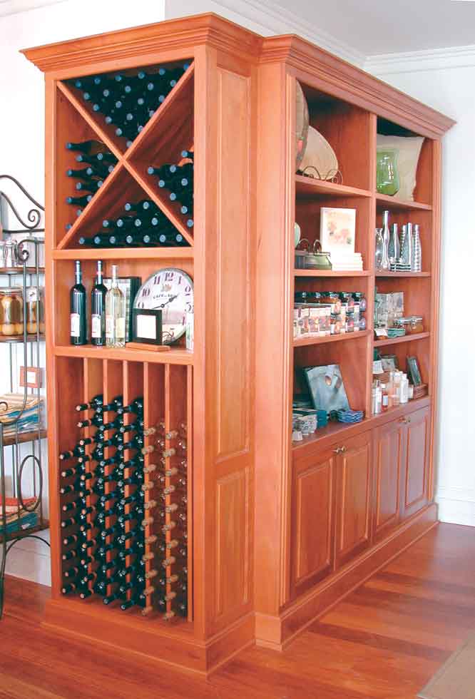
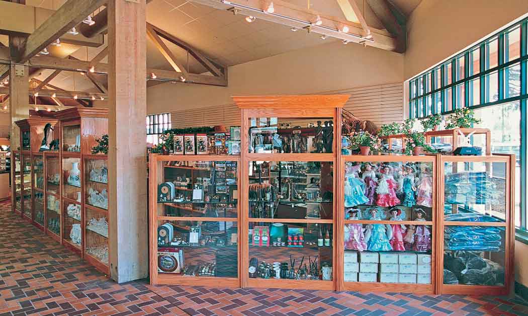
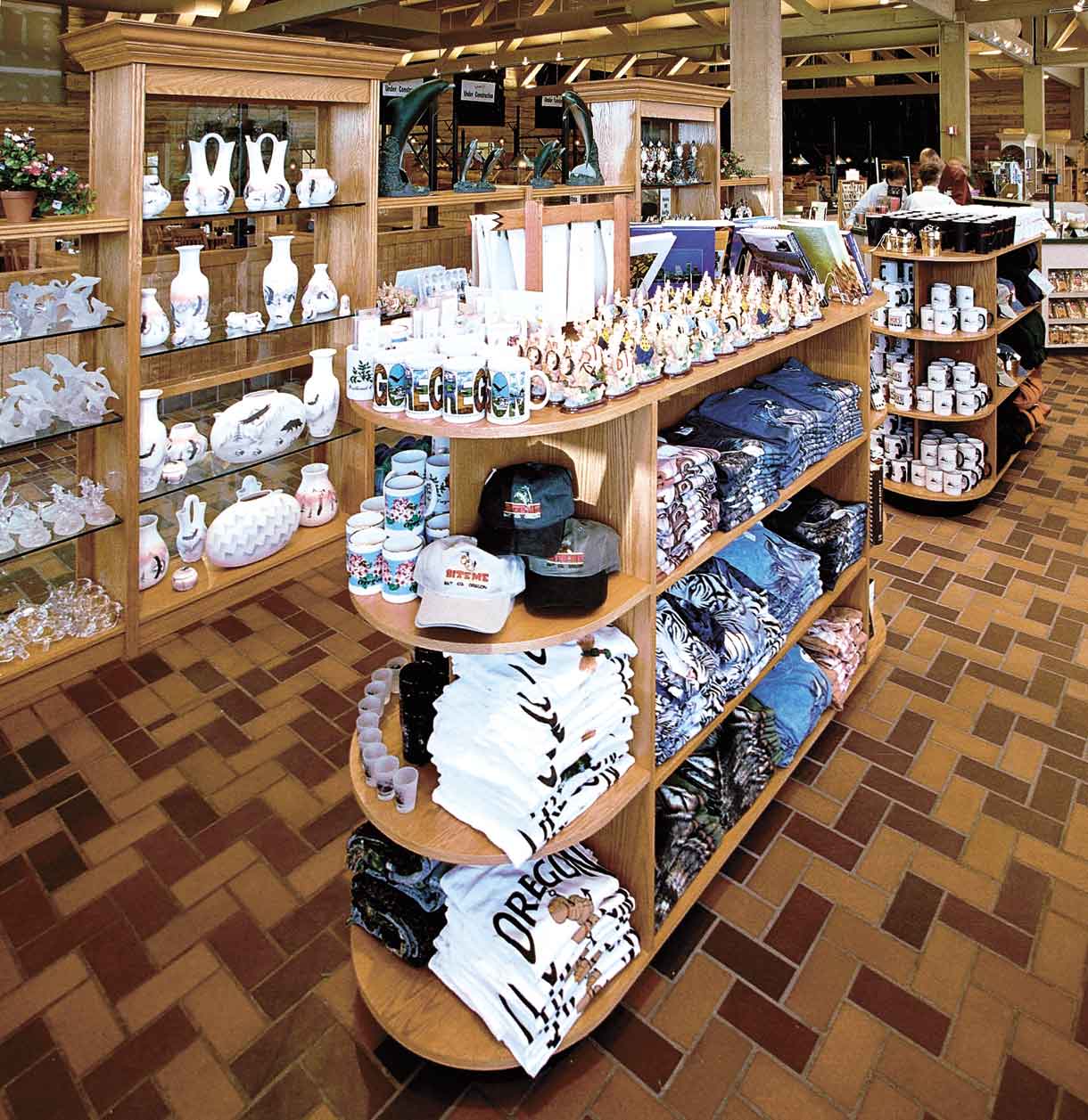
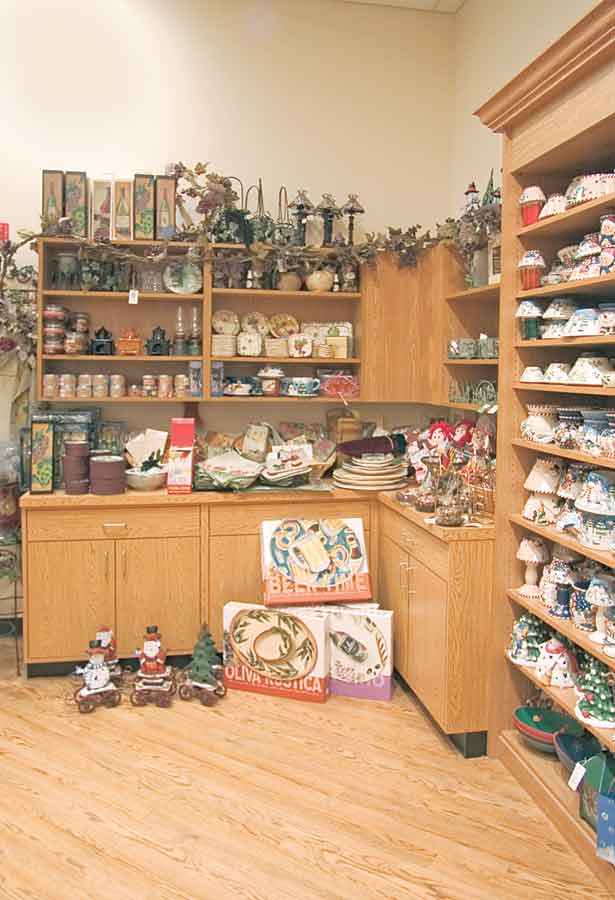
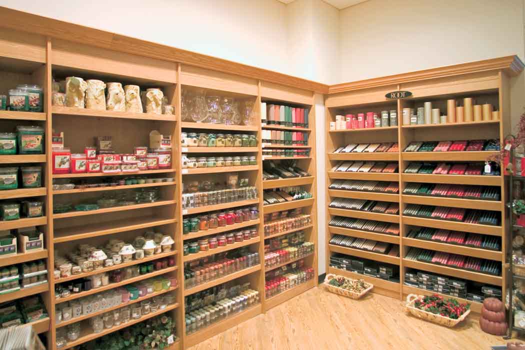
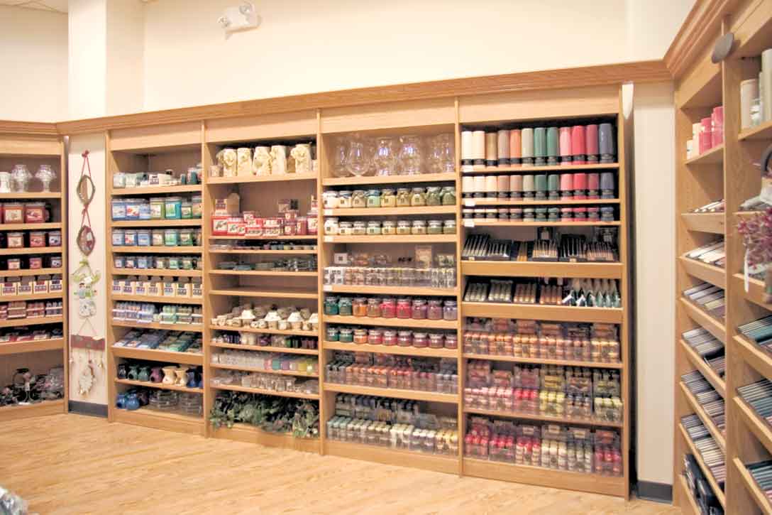
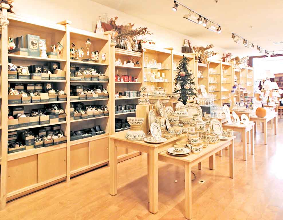
Gallery Photos